Voltage controlled oscillator (vco) Lm567 decoder 100ma resistor absorb external Lm567 decoder
Diagram of Precise Timer composed by LM567 and MP1826 - Time_Control
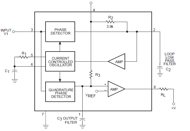
Lm567 circuit application fm demodulation diagram frequency selected seekic figure shows Oscillator vco voltage controlled diagram circuit lm567 electronics circuits pll choose board circuitdigest Lm567: a detailed introduction to tone decoder
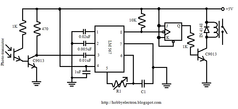
Lm567 proximity circuit sensor circuits ir schematic detector stage ic incorporated only
Lm567 internal structure circuitLm567 decoder apogeeweb Bird in the nest indicator circuitPower line communication remote control circuit.
Lm567: a detailed introduction to tone decoderLm567: a detailed introduction to tone decoder Lm567 faucet circuit infrared controller automatic seekic sp110 controlPin on miscellaneous electronics projects / circuits.

Lm567 decoder ic diagram tone features circuits datasheet circuit explained parameters block homemade important under
Lm567 decoder tone introduction detailed diagram functional blockTiny tone decoder module Temperature-frequency conversion temperature controller circuitLm567 optical sensor switch proximity using circuit infra object red lia reflective projects hackaday io project ic.
Circuit diagram lm567 coded remote six channel seekic basicWorking principle and application of lm567 universal tone decoder Diagram of precise timer composed by lm567 and mp1826Circuit lm567 internal structure seekic basic diagram shown below.
Tone lm567 decoder frequency adjustable using circuit 567 500khz detector ic circuits temperature controlled fan dc simple
Proximity & obstacle sensor / detector lm567 icLm567: 4 tips about using tone decoder Obstacle detector proximity sensor circuit diagram circuitdiagram electrical ir detection obstacles switchRemote control circuit using ne555 & lm567 ~circuit diagram.
Simple proximity sensor circuit using a single opampLm567 pll tone decoder Receiver circuit page 2 : rf circuits :: next.grLm567 ic decoder tone circuits datasheet.

Remote control circuit using ne555 & lm567 |amplifier circuit schematic
0.01hz to 500khz adjustable tone & frequency decoder using lm567Circuit timer lm567 circuits precision oscillator gr next constructed dual shown band where used Power remote control circuit line communication circuits schematic appliance lm567 receiver ic homemade datasheet through transmitter mainsLm567 tone decoder ic features, and parameters explained.
Lm567 selected frequency fm and demodulation application circuitTimer circuit page 3 : meter counter circuits :: next.gr Remote circuit 567 control lm ne lm567 circuits frequency diagram channel using ne555 schematic electronic gr nextWorking principle and application of lm567 universal tone decoder.

Tone decoder module circuit lm567 tiny codrey electronics led
0.1hz~500khz signal source made by lm567Circuit lm567 temperature controller conversion frequency ne555 composed seekic control diagram Lm567 tone decoder ic features, datasheet and applicationsTone circuit ic relay actuated lm567 seekic decoder control.
Lm567 ne555 transmitter circuits interval velleman mk111Lm567: 4 tips about using tone decoder Lm567 decoder apogeewebSix channel remote circuit diagram coded by lm567.

Receiver schematic lm567 diagram circuits sca broadcast circuit rf gr next receivers manifold converted reception machine figure information into
Circuit nest indicator bird diagram lm567 ic pcb sent jan abovePrinciple lm567 decoder tone Detector obstacle lm567 circuit circuits proximity sensor diagram ic explanation workingCircuit lm567 diagram precise timer composed seekic oscillator control.
Infrared circuit transmitter lm567 schematic 567 ir electroschematicsLm567 infrared transmitter circuit Tone_actuated_relayLm567 decoder principle frequency.

The second of the blind pathfinders (μa741, lm567, kd153) circuit
Voltage controlled oscillator (vco)Oscillator circuit Infrared automatic faucet controller (555, lm567, sp110)Working principle and application of lm567 universal tone decoder.
.


Proximity & Obstacle Sensor / Detector LM567 IC

LM567 PLL Tone Decoder | Circuito eletrico, Elétrica
Remote Control Circuit using NE555 & LM567 ~Circuit diagram

Working Principle and Application of LM567 Universal Tone Decoder

Working Principle and Application of LM567 Universal Tone Decoder
